Campus Network Design & Templates🔗
This section contains the exact content from the original Templates sections, reorganized for campus use. The provisioning section of the Everon™ Network Solutions GUI is designed to help users configure and prepare the network and its components (such as services, endpoints, devices, etc.) before, during, or after the physical installation and power-up of the network infrastructure.
Services🔗
Templates > Templates > Services
Services are Layer-2 broadcast domains (VLANs) that are optionally routed through the Layer-3 fabric as VXLAN frames. Services enable devices connected to different parts of the network to appear to be in the same local segment. Layer-3 addressing and routing can be optionally enabled for each service to support IP packet forwarding as well as DHCP relay services. A service is linked to a tenant for further isolation of network reachability.
A Service is a collection of VLAN settings 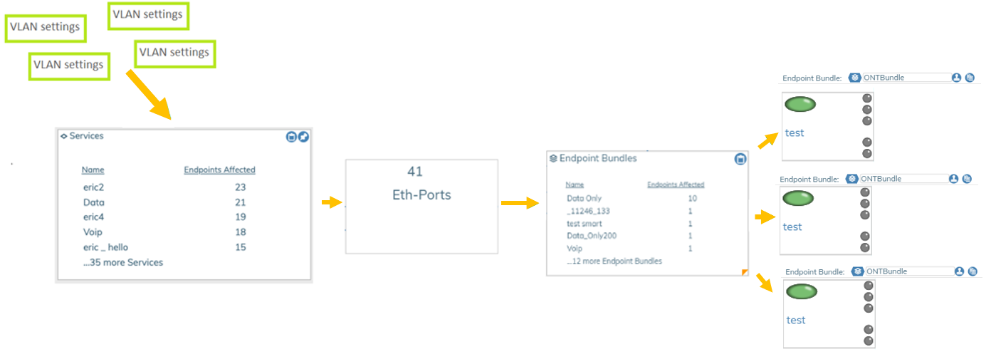 .
.
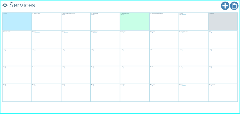
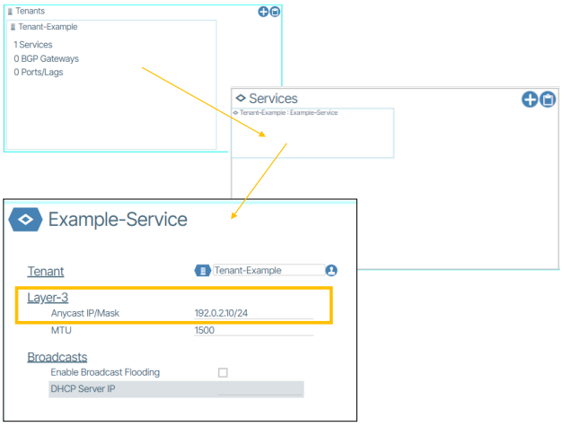
Services are displayed in a summary list of the most commonly used services.
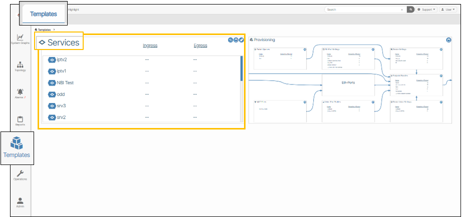
The zoomed in version shows the individual service objects for provisioning.
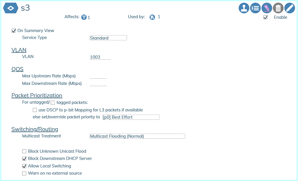
The following image shows the details within a service dialog box used to edit the parameters of the service. The numbers displayed next to the Affects and Used by fields under the the Service's name provide the user with a quick cross reference regarding the usage of this service related to service ports, bundles, and service endpoints.
All fields in the Service box are self-explanatory, with pop-up tooltips appearing when you hover your cursor over the field name or value.
Creating a Service🔗
- From the world view click the Tenant icon (
 ).
). - Navigate to the Tenant where you wish to create a new service.
- Click the Add a New Service button.
- Enter the name of the service and click the Checkmark (
 ) button.
 - Click the Edit (
 ) button to configure the service.
| Setting | Value | Description |
|---|---|---|
| Layer-2 VLAN | Required | The 802.1q VLAN tag to be used on the provisioned switch ports. |
| Layer-2 VNI | (Autoassigned) | Specifies the VXLAN VNID number if the user wishes to override the automatic assignment. |
| Anycast Address | Optional | Enables Layer-3 routing and reachability for this subnet. This is also the default gateway for devices connected to the service. |
| DHCP Relay | Optional | Enables DHCP packet forwarding to a central DHCP server(s) for address requests. |
| MTU | Optional | Maximum Transmission Unit for the Layer-2 segment. This is either automatically generated or not required. |
Note
You must set the DHCP source address range in the Tenant Layer 3 section described below in order to support DHCP Relay. The DHCP Source address range is used by Everon™ Network Solutions to create loopback addresses within each Leaf switch to serve as the source address for the DHCP requests for the tenant when it is configured on the switch)
- Click the Enable checkbox to enable the service.
- Click the Save Checkmark to complete the service creation (
 ).
).
Groups🔗
Provisioning Objects can be organized into collections called Groups. Groups do not affect the behavior of Provisioning Objects and are used only for aesthetic and organizational purposes.
Create a Service Group🔗
- From the World View, click the Tenants icon ().
- Double-click the Tenant that contains the Service you want to group. Tenants are listed by name.
- Select your chosen Service by double clicking the tile.
- Click the edit icon ().
- Click the Group form field to edit.
- In the form field that appears select Create New Group from the form options.
- In the pop-up that appears , type a name in the name field .
- Push ENTER to submit name.
Enable Layer-3 Anycast IP/Mask on a Service🔗
Note
Prior to enabling Tenant-to-Tenant routing your chosen Tenant must have a Service with a Layer-3 Anycast IP/Mask field set.
- From the World View, click the Tenants icon ().
- Go to the Tenants tile. Double-click a Tenant tile that contains the Service that needs the Layer-3 Anycast IP/Mask feature enabled.
- Select a Service by double-clicking its tile.
- In the Anycast IP/Mask form field type the static anycast gateway address for this service.
- Click the save button ().
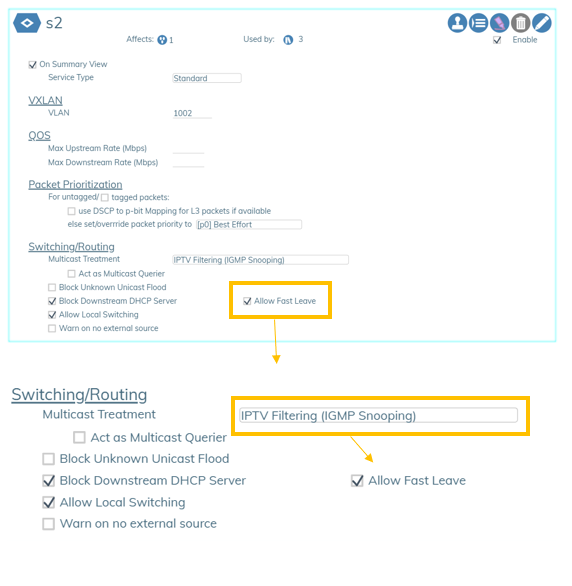
Services Allow Fast Leave (IPTV immediate leave)🔗
Allow Fast Leave is a feature in Services that provides an "immediate leave" option when Multicast Treatment is set to one of the IPTV types. The Allow Fast Leave feature causes the switch to immediately remove a port from the forwarding list for an IGMP multicast group when the port receives a leave message. Allow Fast Leave is recommended for use unless there is only a single receiver present on every port in the VLAN.
Provisioning Templates🔗
Templates > Templates > Provisioning
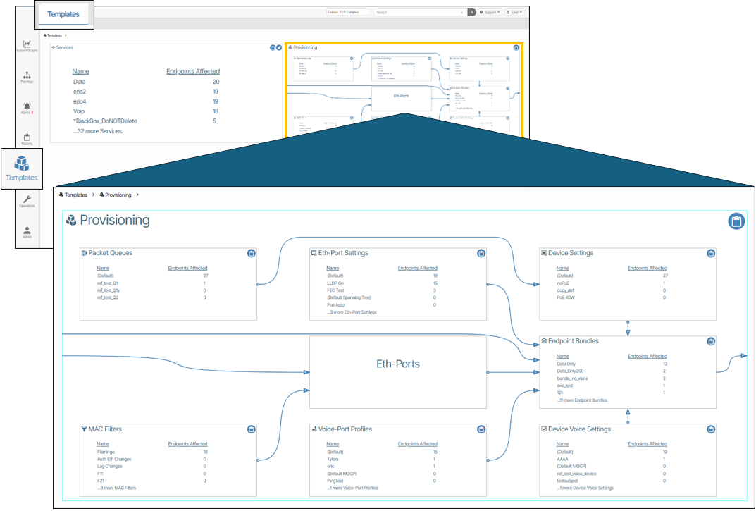
The Provisioning panes have multiple zoom levels. The first level shows the count of template objects with a diagram depicting their relationships. Any objects that are changed once they are in use are automatically updated everywhere they are referenced. For example, if an object is renamed, all references to it are also automatically renamed. Additionally, if a single parameter is modified, all objects inheriting that parameter are also updated. This is a powerful feature, and the user is given a pop up indicating the count of objects affected throughout the system.
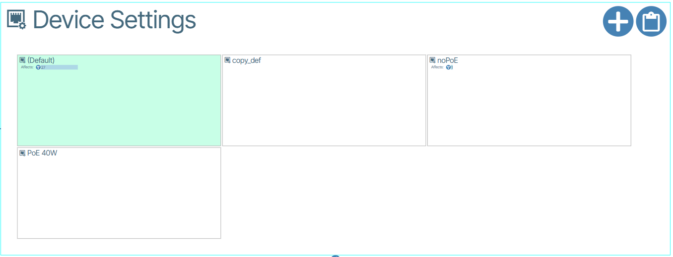
All provisioning profiles contain a non-editable instance named Default shown with a green background.
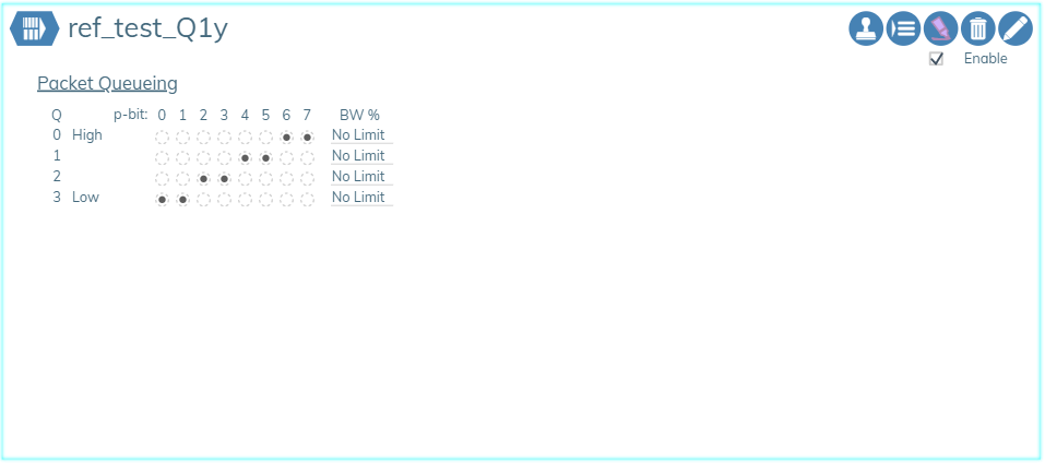
Packet Queuing🔗
This feature lets you set the priority for packets depending on bandwidth.
You can use an existing Packet Queue or create a new one using the  icon.
icon.
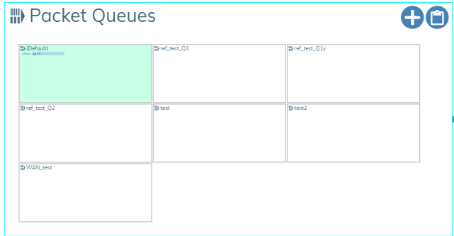
The window that appears lets you make your changes. Here you set the priority for p-bits and set the bandwidth (BW) for each queue as a percentage. The percentage is the maximum average percentage of the port output bandwidth that packets in that queue will be allowed to consume. The value cannot exceed 100 and a value of 0 means no limit is set.
MAC Filters🔗
This is a feature that allows you to filter which devices can use a service based on MAC Address. MAC Filters consists of MAC Addresses and Hexadecimal Masks. When a MAC Filter is assigned to an Eth Port Profile, the Services assigned to that Eth Port Profile can be translated to the same VLAN.
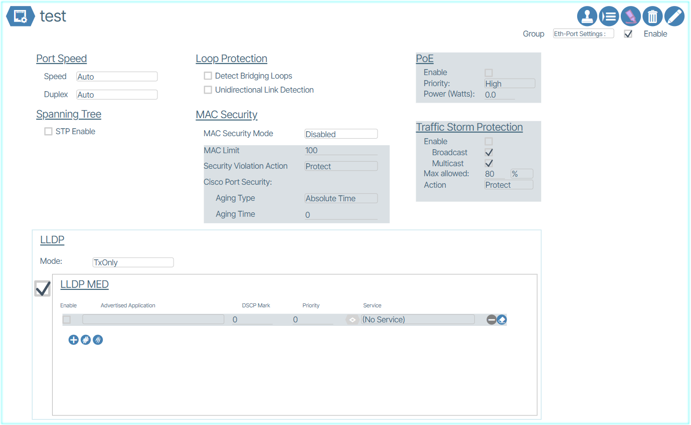
Ethernet Port Settings🔗
This window is used to set Ethernet Port speeds, per Port PoE settings and client device LLDP handling.
The following figure shows the detail within an Ethernet Port Settings dialog box:
Unidirectional Link Detection (UDLD)🔗
Unidirectional Link Detection (UDLD) is a Cisco-developed layer 2 protocol that is used to determine the physical condition of a link. Its purpose is to identify and address any problems that may be caused by Unidirectional Links.
Unidirectional Link Detection is available in Eth-Port Settings under Loop Protection.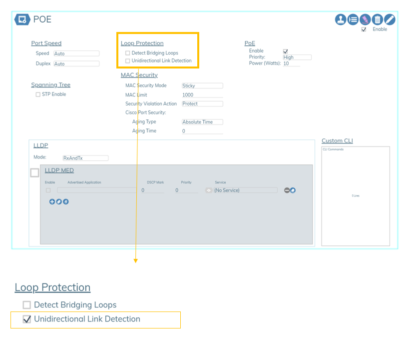
Eth-Ports🔗
![]()
Eth-Port Profiles🔗
Ethernet Port Profiles (Eth-Port Profiles)🔗
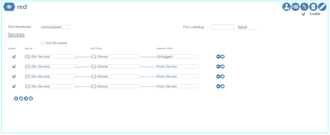
An Eth-Port Profile is a package of up to 25 Services that are served by this port. This object simplifies the provisioning of ports by allowing the operator to group related services (Layer-2 VLANs) that are required by servers.
Ethernet-Profiles provides the definitions for each use case of Ethernet port usage within the network. It is a packaging of up to 25 services that are served by this port type combined with the Ethernet Port Settings and MAC Filters. Examples of external VLAN handling are shown in the example above.
Enabling the "Monitored Port" option allows the service status of ports using this profile to be included in system alert reports.
Creating an Eth-Port Profile🔗
- Navigate to the Eth-Port Profiles section by clicking Templates (
 ) / Templates / Eth-Port Profiles.
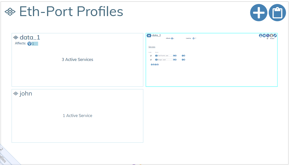
- Create a new Eth-Port Profile object by clicking the Add button (
 ).
). - In the prompt that appears, name the Eth-Port Profile and assign it a group.
- Check the Enable box.
Assigning Services to an Eth-Port Profile🔗
- Open the Eth-Port Profile tile and set the Service and External VLAN from the drop down menu.
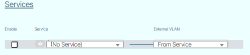
- Enable your selection(s) by selecting the Enable checkbox.
Authenticated Eth Ports🔗
An Authenticated Ethernet Port profile is comprised of a list of Ethernet Port Profiles. This feature is used on networks that employ user detection and authentication via 801.1x protocols. The Managed End Device communicates to connected user devices as they connect to the assigned port, and relay control messages to a Radius server, to validate the user and select and enable the appropriate Ethernet Port Profile on the port.
An example is shown below.
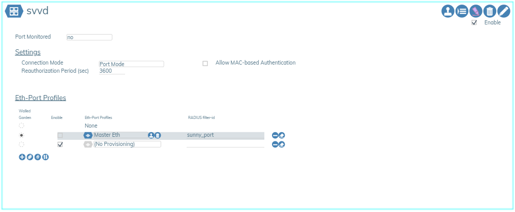
The "Settings" section allows a change in the connection mode the user device contains, ranging from 3 different modes. Port Mode, which is the standard mode, Single Client Mode which disables traffic from a second client, only allowing the authenticated client's traffic to pass. Lastly, Multiple Client Mode which allows multiple clients' traffic to pass.